AHD MOBILE DVR
User Manual
(MR9504)
Catalogue
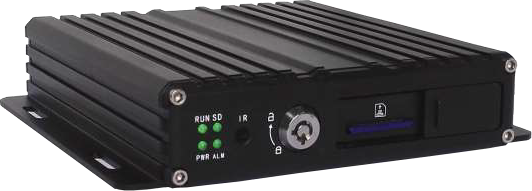
MR9504 is a DVR designed for Analog HD vehicle monitoring. With built-in high performance image processor and advanced H.264 video compression technology, it provides AHD video recording, storage and playback solution. It has built-in WiFi module (optional) for remote monitoring, analysis and management. It comes with smart power management system which can recognize the power type automatically. When detected the battery’s voltage is lower than the gaven value, the device will shutdown automatically and keep ultralow standby consumption.
Device Installation
Please refer to “AHD MOBILE DVR Hardware User Manual (MR9504)” for the SD card installation and cables connection.
User Login
Right click the mouse, you will call out the login interface, please input your UserName, Password, and select your language, click “OK” to login the menu. (The default UserName is admin, without Password), see as following:
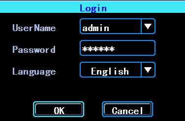
Figure 1. User login Interface
Right click the mouse, select “Menu” to start setup in the menu, see as following:
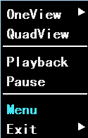
Figure 2. System menu
“Menu” is the primary menu of the system setup and control, see as following:
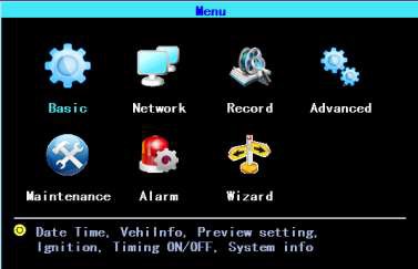
Figure 3. Primary menu
Set up the System time
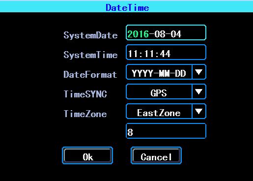
Path: Basic->DateTime, see as following:
Figure 4. System date and time
TimeSYNC: Date and Time can be synchronized with GPS/BD
Set up cameras
Path: Menu->Record->Mode. Please set up your cameras’ SignalType, Valid/Invalid. The DVR works with both AHD and general cameras. If you use AHD cameras, please select the first Type, if you use general cameras, please select the third Type, if you use both of general and AHD cameras, please select the second Type. See as following:
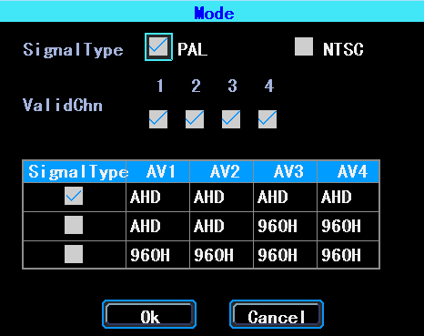
Figure 5. SignalType setup
PS: If your cameras don’t display image on the monitor, please check this setup.
Wizard
Path: Menu->Wizard. This Wizard will help you to quick set up the device connect with the server. If your device is without WiFi function, you can ignore the step 1/4 and begin with step 2/4.
Vehicle Information setup
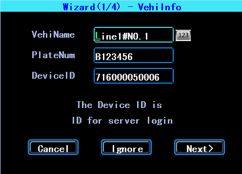
Figure 6. Wizard-Vehicle Information Setup
The DVR is using “Device ID” to connect with the server, so please input the correct DeviceID which was registered on the server for your device. The user can modify the VehicleName and PlateNumber according to their requirement. The PlateNumber is the vehicle’s plate number, and it will be displayed in the video.
DiskManagement
SD card need to be formated in the device when using it for the first time. If the SD card was not detected by the device, please check the SD card lock and make sure it is well locked.
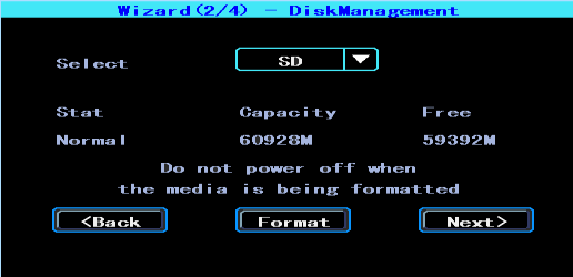
Figure 7. Wizard-DiskManagement
WIFI Setup
The device can save maximum 6 WiFi ESSID (Access Points). It will search, match, connect, and switch automatically. Click the corresponding blank to start WiFi setup. Then click “Search” you will see the available WiFi around your area, select the one your want to connect and input the password and save it.
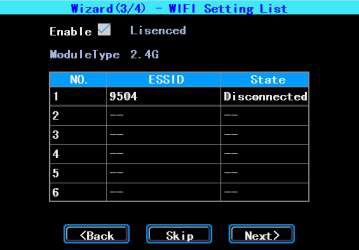
Figure 8. WiFi setup list
Server setup
IP (or Domain) is your server’s IP (or Domain), the Port should be same with your server setup.
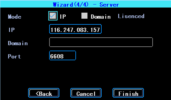
Figure 9. Wizard-Server Setup
NetState
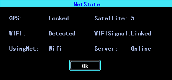
Path: Menu->Network->NetState. You can check the state of the network connection of your device here.
Figure 10. NetState
Server: Online, it means the device connected with the server.
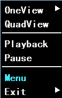
Figure 11. System menu
Video Playback
The device supports one channel video playback, Select “Playback” in the System menu, then you will get the video searching interface, please search the video according to your requirement.
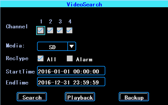
Figure 12. Video Search
PS: The system will only show the latest 4,000 pcs of video files
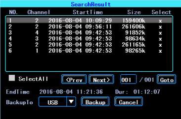
Figure 13. Video Search Result
Video playback
Double click the video file in the video Search result Interface to playback the video.
Video backup
Select the video files in the video search results interface and use your U disk or SD card to backup the videos. (The device supports USB time-delay detecting, you can insert the USB disk after you setted up and clicked the “Backup” button.)
Basic Setup
The basic setup includes the very basic setup items such as DateTime, Vehicle Information, and Preview Etc., See as following:
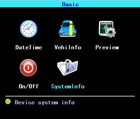
Figure 14. Basic setup
Date time setup
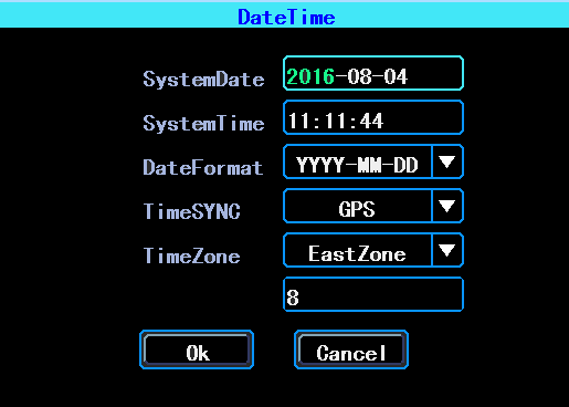
Figure 15. Date time setup
Time synchronization: The system’s date and time can be synchronized with GPS/BD.
Vehicle information
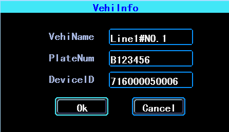
Figure 16. Vehicle information
Device ID: It is the ID used to connect your device with the server. It should be the same ID which you registered your device on the server.
Preview setup
Here you can setup the information which you want to overlay on the Preview image (please note this is not overlayed on the recording image)
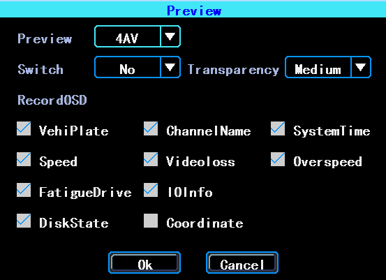
Figure 17. Preview setup
On/Off Setting
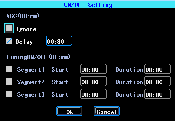
Figure 18. ON/OFFsetting setup
PS: The device’s power cable should be connected as per the Hardware User Manual, otherwise, the On/Off setting will not work.
System information
System information includes: Device Model, Serial Number, Hardware & Firmware version etc.
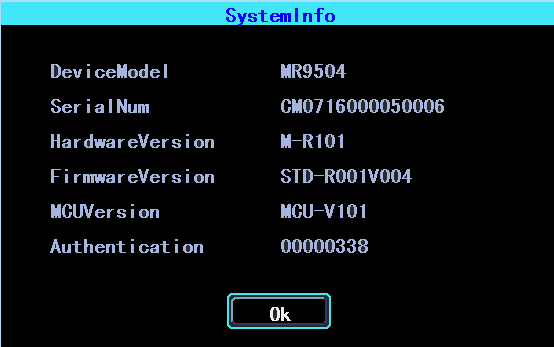
Figure 19. System information
Network setup
Network setup: This interface is used to set up the parameters which are requested to connect the device with the server.
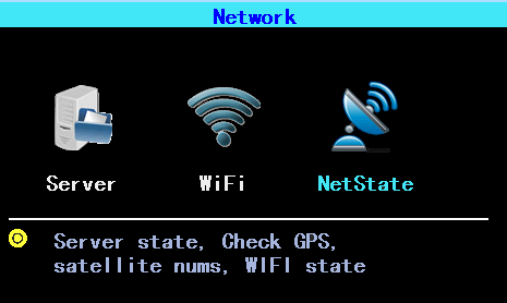
Figure 20. Network setup
Server setup
IP/Domain is the ip or domain of your device’s server.
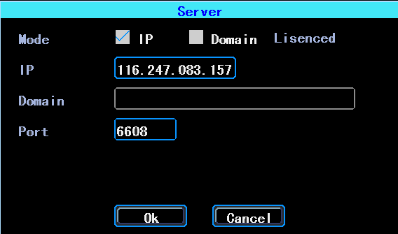
Figure 21. Server setup
WIFI Setup
The device can save maximum 6 WiFi ESSID (Access Points). It will search, match, connect, and switch automatically. Click the corresponding blank to start WiFi setup. Then click “Search” you will see the available WiFi around your area, select the one your want to connect and input the password and save it.
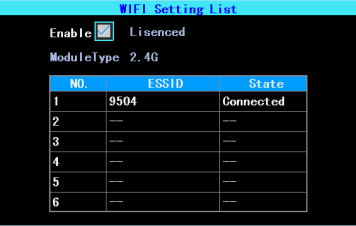
Figure 22. WIFI Setting list
You can input the ESSID of the WiFi AP but you can also click “Search” to search the available WiFi ESSIDs around your area.
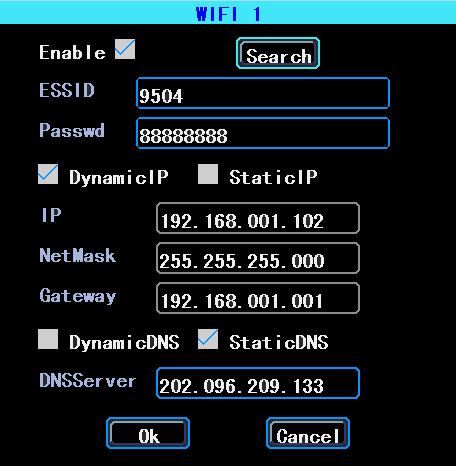
Figure 23. WIFI Setup
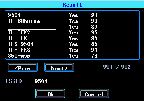
Figure 24. WIFI Search result
Network State
You can check the state of the network connection of your device here.
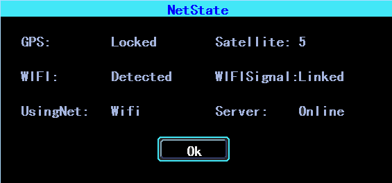
Figure 25. NetState
Recording Setup
Recording setup includes Mode, Main Stream, Sub Stream, Recording OSD, Image, storage.
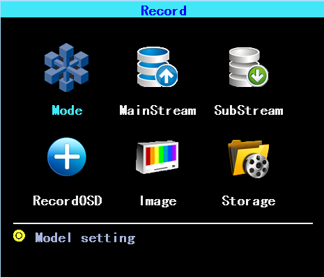
Figure 26. Recording setup
Mode setup
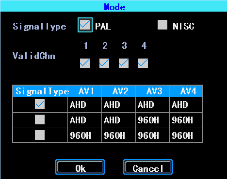
Figure 27. Mode setup
Please set up your cameras’ SignalType, Valid/Invalid. The DVR works with both AHD and general cameras. If you use AHD cameras, please select the first Type, if you use general cameras, please select the third Type, if you use both of general and AHD cameras, please select the second Type.
MainStream
Main Stream is stored in local disk. This interface shows the current Main Stream
setting and the corresponding storage size, you can click any line to set up the corresponding parameters.
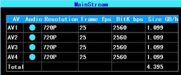
Figure 28. Main stream list
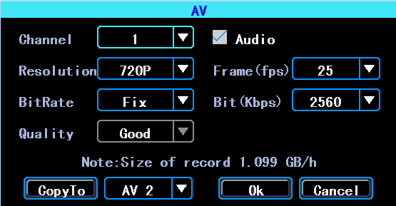
Figure 29. MainStream AV setup
PS: If BitRate is bigger, the corresponding channel’s storage size will be bigger.
SubStream
SubStream is used for network transmission and backup in local disk.
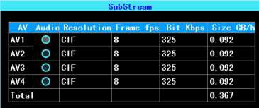
Figure 30. SubStream setup
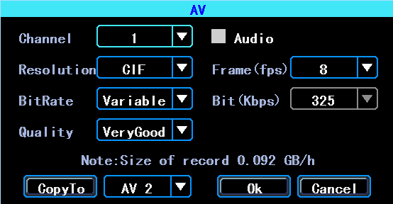
Figure 31. SubStream AV setup
Recording OSD
Recording OSD is used to overlay the information to video recording.
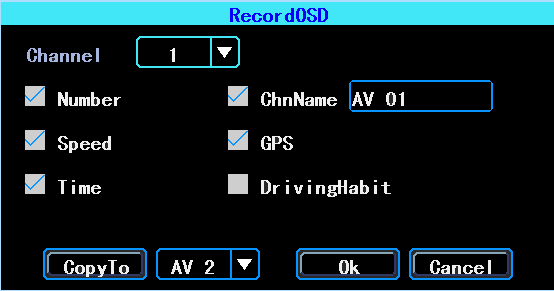
Figure 32. Recording OSD
Image setup
Image setup is used to adjust to camera’s image effect, please set up it carefully.
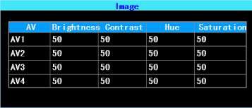
Figure 33. Image setup
Storage setup
The device supports dual storage. Both of the MainStream and SubStream can be stored in local disk, but each disk can only store one type of stream.
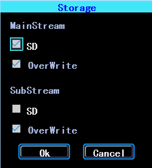
Figure 34. Storage setup
Advanced setup
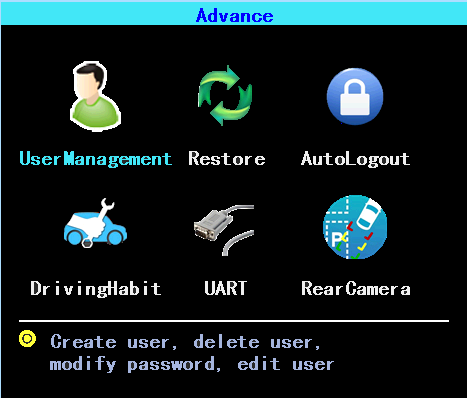
Figure 35. Advanced setup
UserManagement
You can add, modify, delete users, and modify the login username and privileges
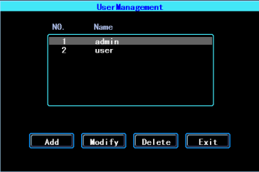
Figure 36. User management
Restore
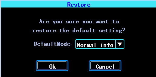
Restore the system setup parameters. System will reboot when restore finished. See as following:
Figure 37. Restore
There are 3 restore modes:
Normal Info: Restore all info except Vehicle info. Vehicle Info: Restore vehicle info only.
All: Restore all info.
Logout
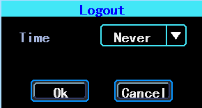
Logout means the current user will logout the system automatically if the user had no operation in the gaven time range.
Figure 38. Logout
UART setting
The device has 1 RS232 Interface.

Figure 39. UART setting list
UART-TTS
Select UART 0 to get into UART setting interface.
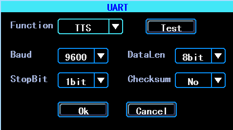
Figure 40. UART setting interface
Select “TTS” in the drop-down box of “Function”, config the parameters as per the picture above.
UART-Serial Net
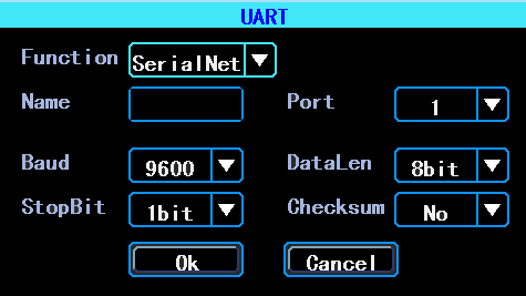
Select UART 0 to get into UART setting interface.
Figure 41. UART setting interface
Select “SerialNet”(PassThrough)in the drop-down box of “Function”. Config the parameters as per the picture above.
Rear Camera setup
Any channel can be used as rear camera, click “Zone” to set up the assistance lines.
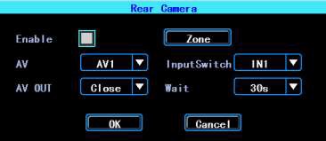
Figure 42. Rear Camera setup
The assistance lines are adjustable (dragging the blue points)

Figure 43. Assistance lines setup
Device maintenance
Device maintenance includes the operation of basic maintenance, such as log inquiry, Disk management, Import/Export the setup and config, system upgrading.
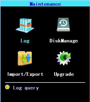
Figure 44. Device maintenance
Log inquiry
Inquiry the system’s running log according to the required Log Type and Time Range.
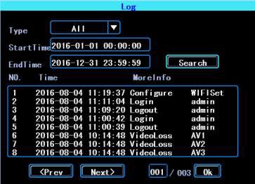
Figure 45. Log inquiry
Disk Management
SD card need to be formatted in the device when you use it for the first time.
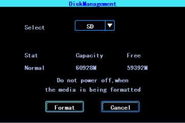
Figure 46. Disk Management
Import/Export
Import/Export is used to import/export the setup and config information for setup in batch.
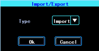
Figure 47. Import/Export
After setted up one device, export the setup parameters with your U disk, then insert the U disk into other device’s USB port and re-power on the device, it will get the setup parameters utomatically. (If you don’t want to re-power on the device, you can import the setup paramaters in menu, see as above)
System upgrading
Format your U disk as FAT32 type and copy the upgrading file to the root directory of the U disk. Then re-power on the device, it will upgrade automatically. If you don’t want to re-power on the device, you can upgrade it in the menu “Import/Export”. Select the upgrading type, click OK, then insert the U disk. The system will detect the U disk and the file and then upgrade automatically.
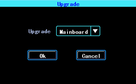
Figure 48. System upgrading

Figure 49. Upgrading progress
PS: You can insert the U disk which with the upgrading file, and then re-power on the device, it will upgrade automatically. You can also upgrade the device remotely from PC CMS software if your device has WiFi function and connected with the server by WiFi.
Alarm setup
Alarm setup interface includes the setting related to all alarm types, such as I/O alarm, Video Loss, Fatigue Driving, Over Speed, Disk error.
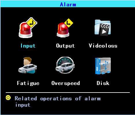
Figure 50. Alarm setup
Input Alarm
The device has 4 alarm inputs, 2 are Positive Trigger, 2 are Negative trigger.
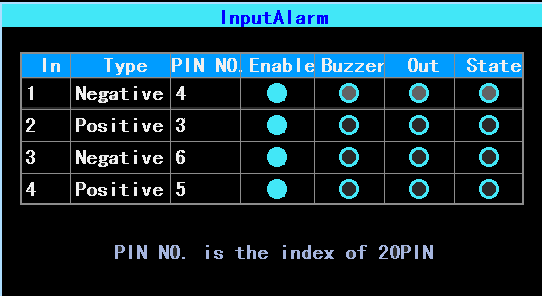
Figure 51. Input Alarm list
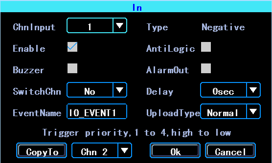
Figure 52. Input Alarm setup
There are three input modes: high level, low level and open. For positive trigger, the normal trigger level is high, but if the reversed logic is enabled, the trigger level is changed to low level and open. It is same for negative trigger.
表1. Alarm Input Trigger status list
| Alarm Trigger | Positive trigger | Negative trigger | |
| Reversed Logic | No | High level | Low level |
| Reversed Logic | Yes | Low level/Open | High level/Open |
Video Loss
Video Loss alarm will be triggered if there is no camera or wrong type camera were connected with a valid channel.
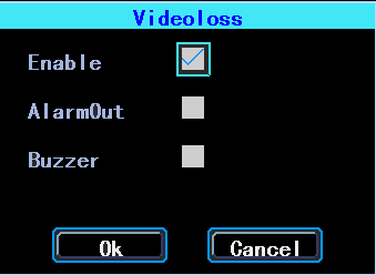
Figure 53. Video Loss alarm setup
FatigueDrivingAlarm
The Fatigue Driving time is calculated since the device was started.
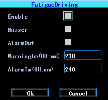
Figure 54. Fatigue Driving alarm setup
OverSpeedAlarm
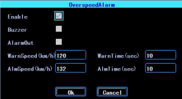
Figure 55. OverSpeedAlarm setup
DiskError
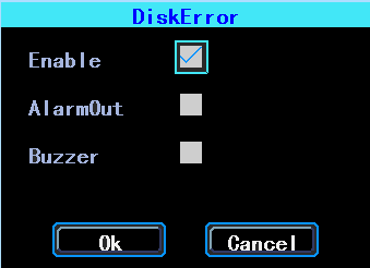
Figure 56. DiskError setup
Chapter 4 Installation Warnings
For safely using and long service life, please respect these Warnings when insalling and using the device:
- When you received the product, please open the box and check the device and accessories. If there is anything damaged or missing, please contact your seller.
- When installing and operating the device, please respect the standard of all electronics and the connecting requests of the vehicle and other devices
- Please double check the input power voltage, it should be 10-36V DC, to avoid the damage caused by wrong voltage.
- The device should work in the permitted temperature and humidity.
- There should be enough space and fire resistant pipes on the external cables of the device to avoid electric leakage caused by abrasion and aging.
- The installation and construction should be compliant with the standard of the government.
